PROBLEM
An autonomous airship has to live on the power it collects. Solar charging, sensing, propulsion and control all have to work together on one airframe.
APPROACH
- I designed custom PCBs that bring ESP32 microcontrollers, solar charge controllers, GPS, an altimeter and a gyroscope into one electrical system.
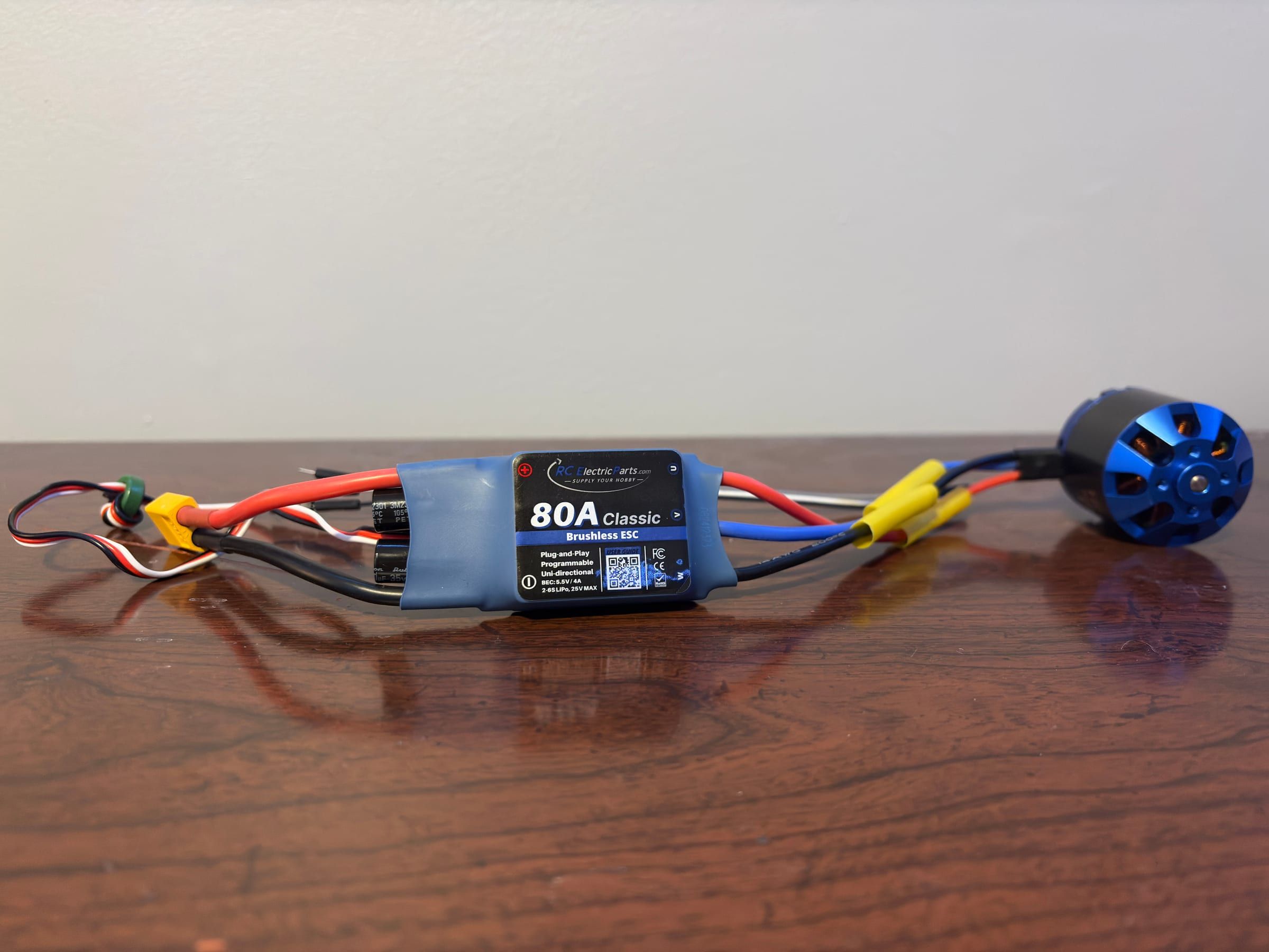
- I wrote the motor control firmware for a thrust-vectoring propulsion system and built aerodynamic models of the airframe.
- I produced the CAD and electrical schematics in SolidWorks and SolidWorks Electrical, and maintained the project’s web documentation.
DESIGN
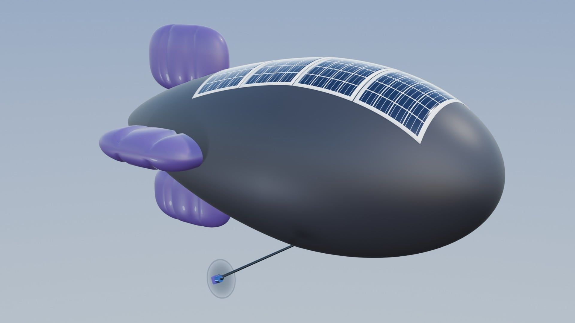
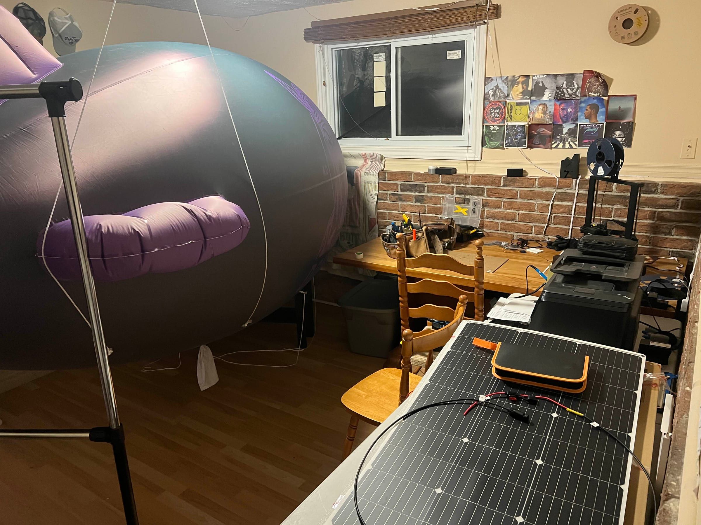
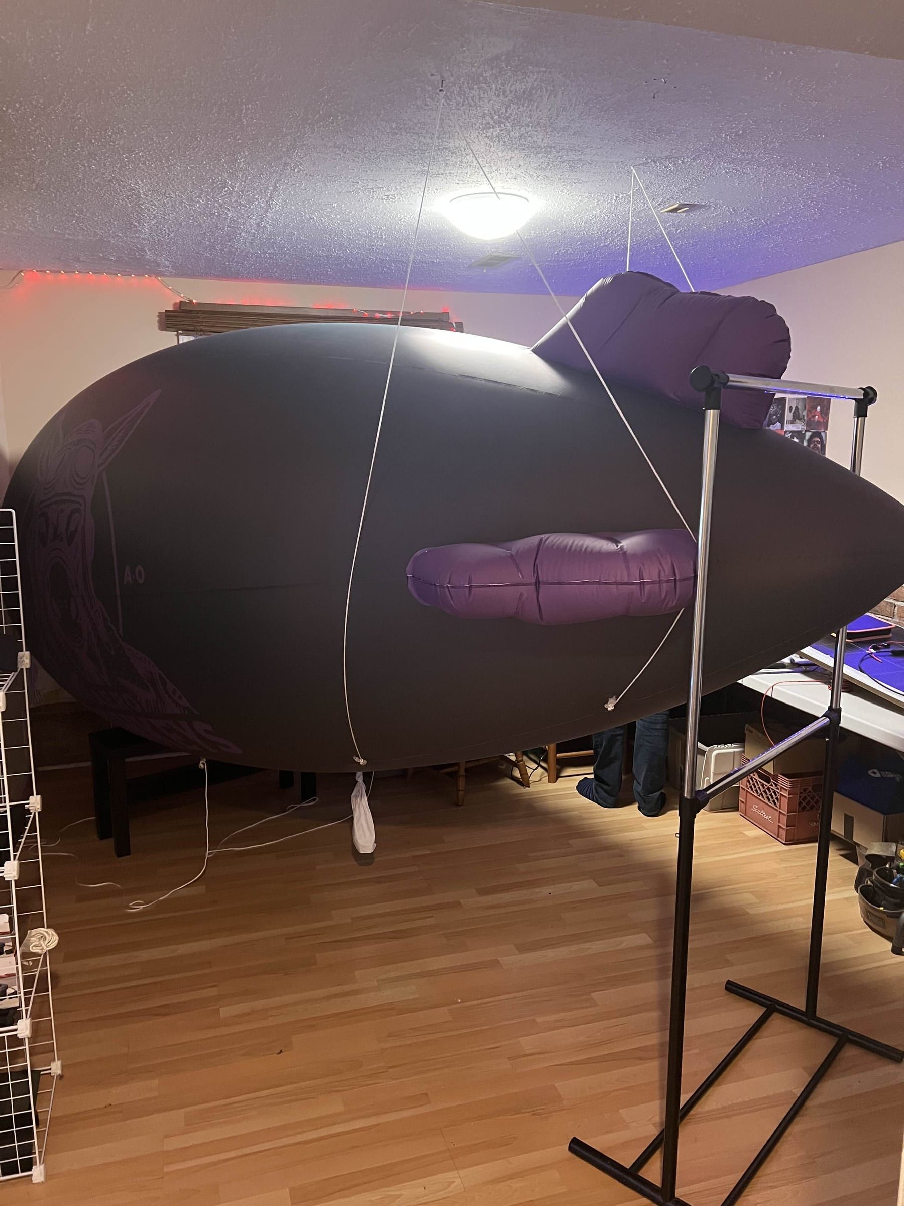
The finished blimp, built in Blender from photos of the envelope and the real mounting plate and motor mounts. Scroll to fly round it and watch the motors tilt.
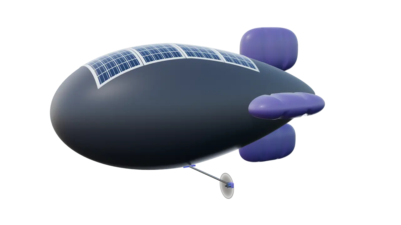
- Envelope 13 ft PVC, inflatable fins
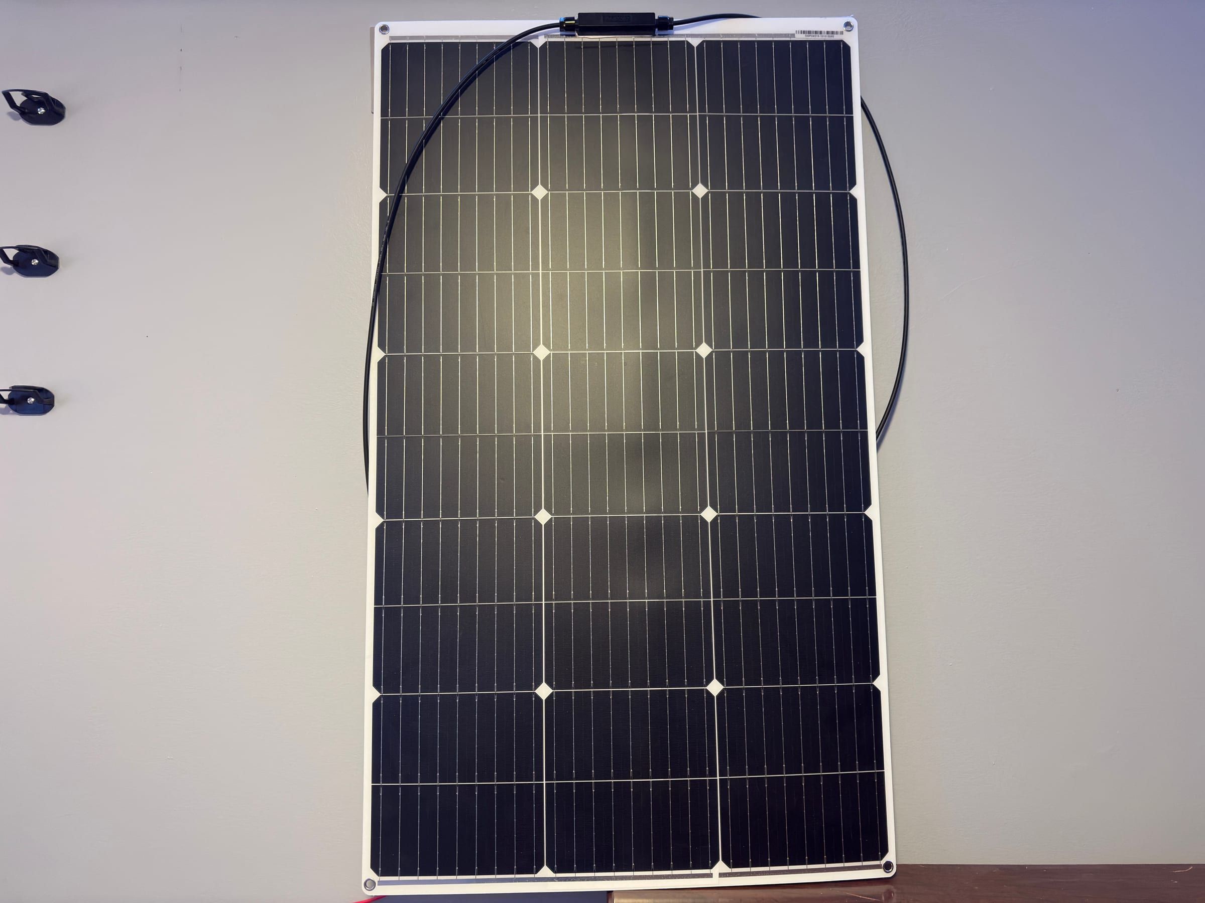
- Solar array 4 × 100 W flexible panels
- Thrust vectoring Motors tilt on 1 m arms
Rendered in Blender. The envelope, plate and motor mounts follow the real parts; the motors, props and arms are stand-ins.
PARTS
Three of the blimp’s parts from the SolidWorks model, rendered in Blender from their STL exports. Scroll to print them layer by layer.
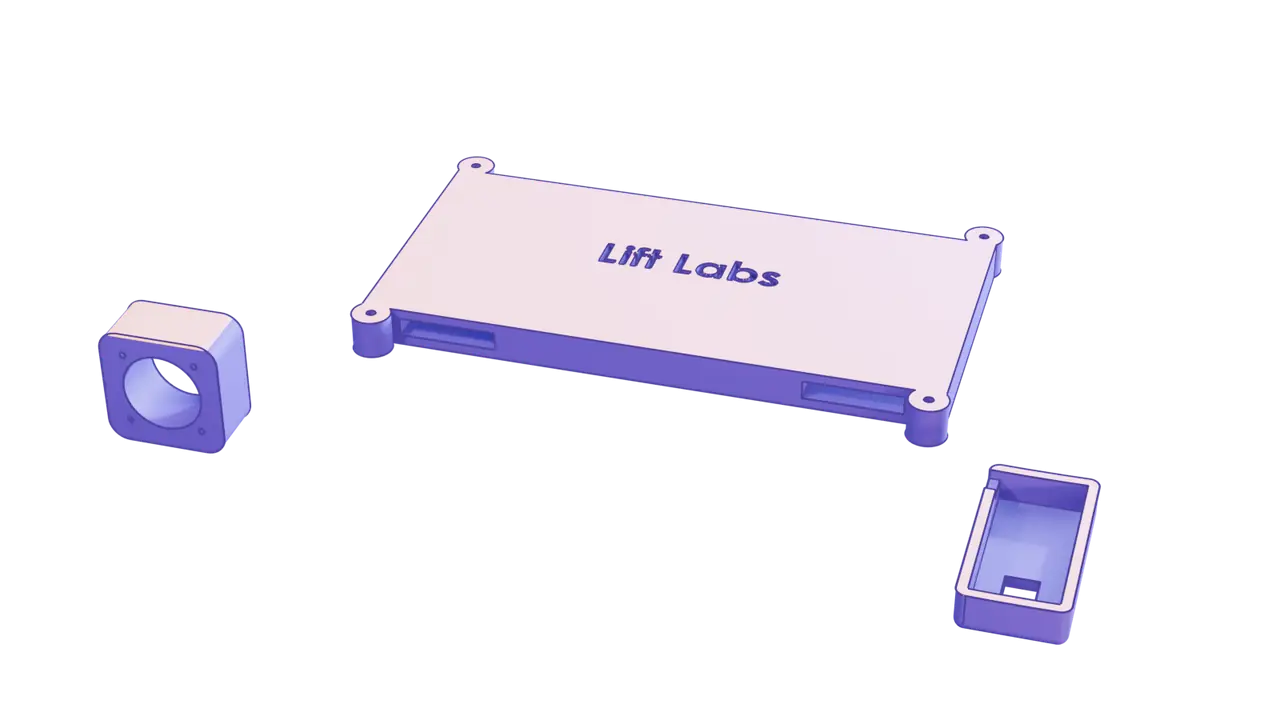
- Motor-to-servo mount 60 × 60 × 30 mm
- Mounting plate 305 × 181 × 20 mm
- GPS enclosure 100 × 50 × 20 mm
Rendered in Blender. The colour and print order are for illustration.
STACK
Hardware and software behind the project.
| Area | What I used |
|---|---|
| Control | ESP32 microcontrollers on custom PCBs |
| Power | Solar charge controllers |
| Sensing | GPS, altimeter and gyroscope |
| Propulsion | Thrust-vectoring motors |
| Area | What I used |
|---|---|
| Firmware | Motor control firmware |
| Modelling | Aerodynamic models of the airframe |
| Design | SolidWorks and SolidWorks Electrical |
RESULTS
- Applied for and secured project funding from the Thompson Engineering Fund.